3D Drawing Setup Example
There is some configuration required to be able to link assets in the NEXUS IC hierarchy to objects in a 3D drawing. Once configured successfully, you will be able to:
Hover over the object in the 3D Drawing to view the NEXUS IC asset name.
Click on an object in the 3D drawing to auto navigate to that asset in the NEXUS IC asset hierarchy.
Display traffic lighting on the 3D drawing objects.
Caution
For optimal performance, an OpenGL graphics card is required on the client machine for this functionality. 3D drawings can take a considerable time to load. We recommend that 3D drawings are simplified as much as possible to reduce file size and load times.
Step 1
The first step is to ensure that the 3D Drawing is configured with an Asset Serial Number attribute.
Using Autocad, create a block which represents a single asset in the NEXUS IC asset hierarchy. For each block, define an attribute (using the ATTDEF command) and populate the attribute with the “Asset Serial Number”.
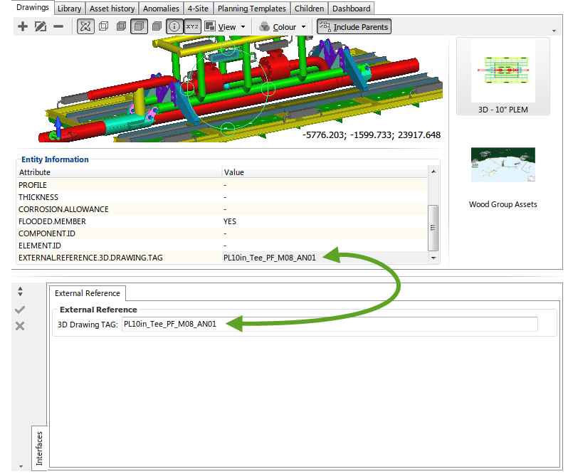
In this example, the attribute in the 3D drawing is titled EXTERNAL.REFERENCE.3D.DRAWING.TAG. The following images illustrate the attributes in Autocad and in NEXUS IC.
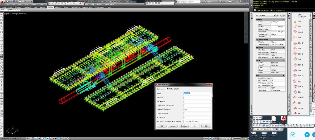
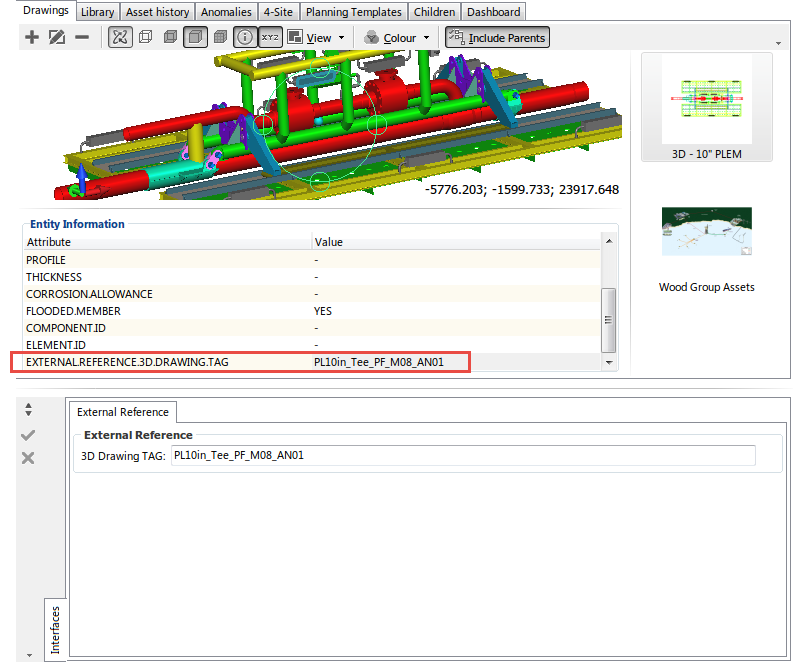
For detailed instructions on how to prepare an Autocad drawing, refer to 3D Drawing Preparation in Autocad.
Step 2
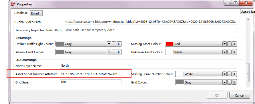
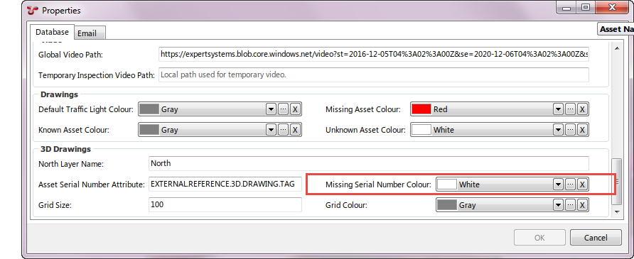
Go to Properties . Type in the 3D Drawing Attribute name which contains the Asset Serial Number information. In this example, the attribute in the 3D drawing is titled EXTERNAL.REFERENCE.3D.DRAWING.TAG.
Step 3
Go to Properties . Select a colour to be displayed for any block where the attribute is defined, but there is no corresponding match in the asset hierarchy in NEXUS.
Step 4
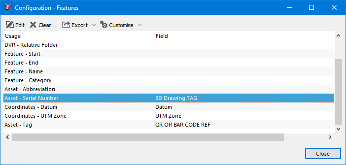
Go to to edit the field. In this example, the AIG field Asset - Serial Number has the 3D Drawing TAG field set, located in the AIG titled External Reference.
Step 5
Ensure that the Asset Serial Number data is populated in the specified AIG field and that the data matches that in the Asset Serial Attribute in the 3D drawing.
